Lesson Objectives: Utilize an Arduino Nano to control the color produced by an RGB LED. Understand the difference in code and wiring for a common anode vs common cathode RGB LED.
Materials Required:
- Breadboard
- Wires
- Microprocessor with cable
- Two RGB LEDs: one cathode and one anode
- Resistors (I used three 100 Ohms resistors, but any three low resistors will work. )
- The below Arduino sketches.
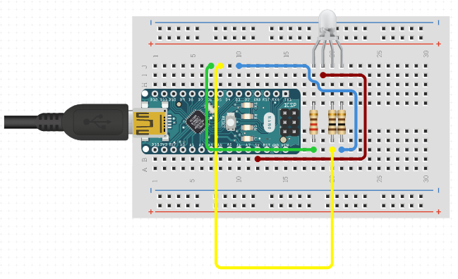
Image of a RGB common anode wired to a Nano on a breadboard:

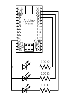
Image of a RGB common anode circuit diagram:

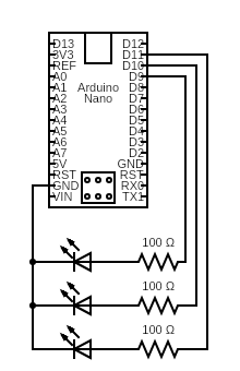
Image of a RGB common cathode circuit diagram:

Code used for RGB common cathode:
/*
Adafruit Arduino - Lesson 3. RGB LED
https://learn.adafruit.com/adafruit-arduino-lesson-3-rgb-leds
*/

int redPin = 11;
int greenPin = 10;
int bluePin = 9;

//uncomment this line if using a Common Anode LED
//#define COMMON_ANODE

void setup()
{
  pinMode(redPin, OUTPUT);
  pinMode(greenPin, OUTPUT);
  pinMode(bluePin, OUTPUT);
}

void loop()
{
  setColor(255, 0, 0);  // red
  delay(1000);
  setColor(0, 255, 0);  // green
  delay(1000);
  setColor(0, 0, 255);  // blue
  delay(1000);
  setColor(255, 255, 0);  // yellow
  delay(1000);
  setColor(80, 0, 80);  // purple
  delay(1000);
  setColor(0, 255, 255);  // aqua
  delay(1000);
}

void setColor(int red, int green, int blue)
{
  #ifdef COMMON_ANODE
    red = 255 - red;
    green = 255 - green;
    blue = 255 - blue;
  #endif
  analogWrite(redPin, red);
  analogWrite(greenPin, green);
  analogWrite(bluePin, blue);
}
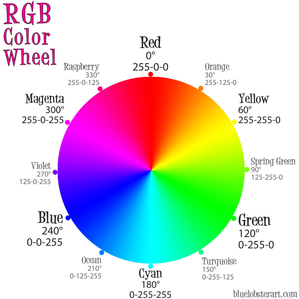
Additive RGB Color Wheel

Helpful links:
- The code used in this lesson was created by Simon Monk with Adafruit.
- It is helpful to find a good website to help choose RGB values to match LED light output.
- I used this page to design the breadboard picture.
- I used this website to design the circuit schematic.