Lesson Objective: Learn how to utilize an operational amplifier to increase the signal in a circuit. Observe the difference in analogRead as compared to digitalRead.
Materials Required:
- Breadboard
- Wires
- Microprocessor with cable
- Resistors (100, 470 and 10k Ohms, or similar)
- Photoresistor (light dependent resistor, mine is a GL5539)
- Op-amp (mine is a Texas Instrument LM358N)
- The below Arduino sketch
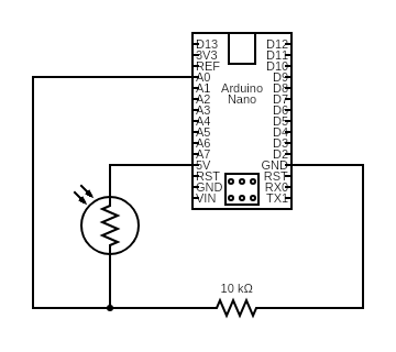
Circuit diagram allowing a simple analogRead of photoresistor voltage drop:

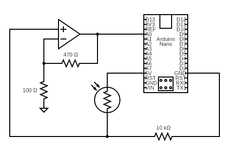
Circuit diagram allowing analogRead of photoresistor voltage drop that has been amplified with an op-amp:

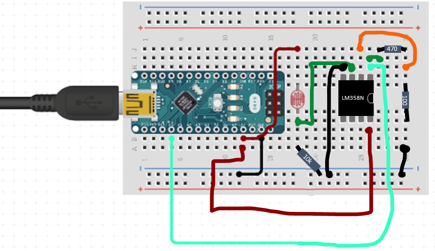
Breadboard configuration for op-amp photoresistor:

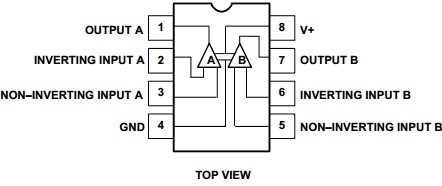
Pin Configuration for LM358N Op-amp:

Arduino sketch for this lesson:
const int sensorPin = A0 ; // select the input pin
int sensorValue = A0;  // Establishes that there is an integer that is called sensorValue. This block of memory on the chip now has a name.

void setup(void) {
   Serial.begin(9600);
   pinMode(sensorPin, INPUT);
}

void loop(void) {
   sensorValue = analogRead(sensorPin); //tells the Arduino that the sensor value is an integer equal to the reading from A0
   Serial.println(sensorValue); //tells the Arduino to print the value that was stored to the serial monitor
   delay(1000);
}
Helpful links:
- Here is a good link with an overview of op-amps.
- I used Circuit.io to design the breadboard picture, except the added drawn wires.
- I used this website to design the circuit schematic. https://www.circuit-diagram.org/editor/