Lesson Objectives: Practice reading a circuit diagram to set up your breadboard. Transmit IR light from an IR emitter and receive this light with an IR sensitive photodiode. Utilize a push button to turn an IR light on or off.
Materials Required:
- Breadboard
- Wires
- Microprocessor with cable
- An LED (any color)
- Resistors (I used 220, 10k, and 1M Ohms resistors. )
- The below Arduino sketches.
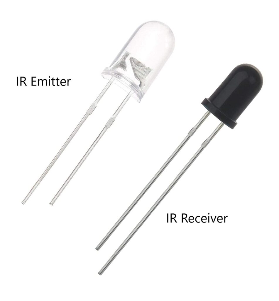
- An IR emitter and IR transmitter

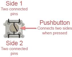
- A push button

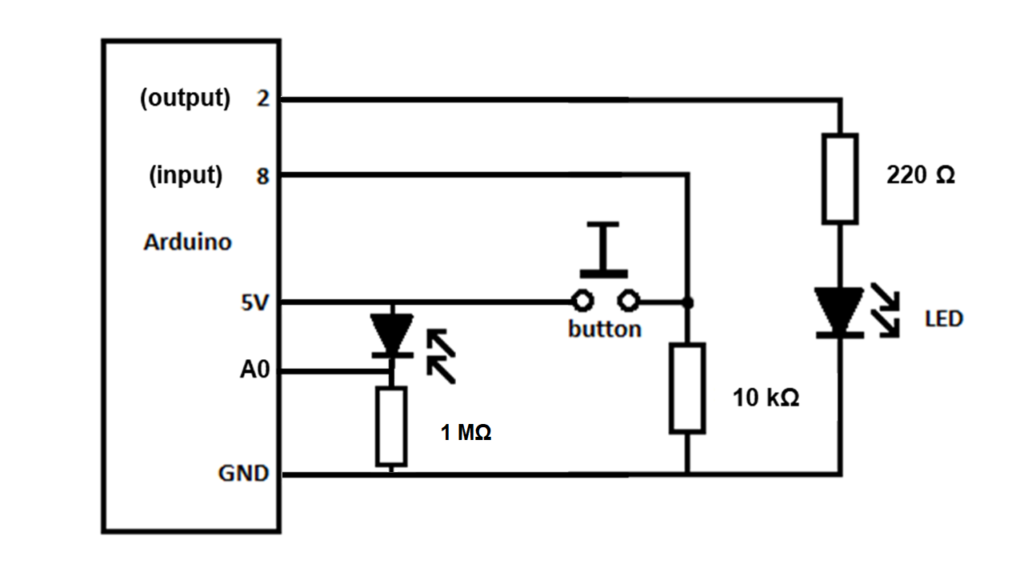
Before watching the video, set up the following circuit which contains two voltage dividers on your breadboard. You will be using digital pins 2 and 8 and analog pin 0. Place your IR receiver where the photodiode is shown with light coming in, as the receiver is really just a photodiode that is sensitive to IR light. Make sure you orient the receiver with the positive lead (longer) closest to power (5 V) and the negative end leading toward ground. Place your resistors where indicated. Place your LED as indicated by the photodiode with light coming out. We will replace this with your IR emitter later in the lesson.
Circuit Diagram for Controlling IR light with a Push Button

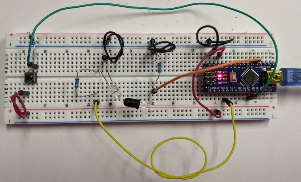
Here is a picture showing the breadboard as I set it up. There are many similar ways to achieve the circuit designed above.

Download the following sketch, which we will use first.
/* sketch 1
turn on a LED when the button is pressed
turn it off when the button is not pressed (or released)
*/
int buttonPin = 8; //the pin where we connect the button
int ledPin = 2; //the pin we connect the LED
int sensorPin = A0;
int sensorValue = 0;

void setup() {
  Serial.begin(9600);
  pinMode(sensorPin, INPUT);
  pinMode(buttonPin, INPUT); //set the button pin as INPUT
  pinMode(ledPin, OUTPUT); //set the LED pin as OUTPUT
}

void loop() {
  sensorValue = analogRead(sensorPin);
   Serial.println(sensorValue);
   delay(1000);
  int stateButton = digitalRead(buttonPin); //read the state of the button
  if(stateButton == 1) { //if is pressed
     digitalWrite(ledPin, HIGH); //write 1 or HIGH to led pin
  } else { //if not pressed
     digitalWrite(ledPin, LOW);  //write 0 or low to led pin
  }
}
Lesson video:
The first sketch we used in this lesson was modified using the code found here. I wanted to change up the code in order to allow the light to remain on after the button was pressed, and then turn off when it was pressed again. It is a good lesson to analyze the original code above and the code found on this link, figuring out how the two were combined to produced the code found below. Download the below sketch for the second part of this lesson.
/*
  State change detection (edge detection)

  Often, you don't need to know the state of a digital input all the time, but
  you just need to know when the input changes from one state to another.
  For example, you want to know when a button goes from OFF to ON. This is called
  state change detection, or edge detection.

  This example shows how to detect when a button or button changes from off to on
  and on to off.

  created  27 Sep 2005
  modified 30 Aug 2011
  by Tom Igoe

  This example code is in the public domain.

  http://www.arduino.cc/en/Tutorial/ButtonStateChange

  The above was modified to allow the button to turn on with a push and off with a push,
  while still monitoring the analogRead at A0. Since the loop is looking for both the sensor Value
  and the buttonState, you should long press the button anytime you want to change the button
  state. Short presses of the button can be missed and not counted.
*/

// this constant won't change:
const int  buttonPin = 8;    // the pin that the pushbutton is attached to
const int ledPin = 2;       // the pin that the LED is attached to

// Variables will change:
int buttonPushCounter = 0;   // counter for the number of button presses
int buttonState = 0;         // current state of the button
int lastButtonState = 0;     // previous state of the button
int sensorPin = A0;
int sensorValue = 0;

void setup() {
  pinMode(sensorPin, INPUT);
  // initialize the button pin as a input:
  pinMode(buttonPin, INPUT);
  // initialize the LED as an output:
  pinMode(ledPin, OUTPUT);
  // initialize serial communication:
  Serial.begin(9600);
}

void loop() {
  sensorValue = analogRead(sensorPin);
   Serial.println(sensorValue);
   delay(1000);

   // read the pushbutton input pin:
    buttonState = digitalRead(buttonPin);
  // compare the buttonState to its previous state
  if (buttonState != lastButtonState) {
    // if the state has changed, increment the counter
    if (buttonState == HIGH) {
      // if the current state is HIGH then the button went from off to on:
      buttonPushCounter++;
          } else {
      // if the current state is LOW then the button went from on to off:
      ;
    }
    // Delay a little bit to avoid bouncing
    delay(50);
  }
  // save the current state as the last state, for next time through the loop
  lastButtonState = buttonState;

  // turns on the LED every two button pushes by checking the modulo of the
  // button push counter. the modulo function gives you the remainder of the
  // division of two numbers. So if the counter is divisible by 2, the remainder is
  // zero and the LED is turned on. Else it is turned off.
  if (buttonPushCounter % 2 == 0) {
    digitalWrite(ledPin, HIGH);
  } else {
    digitalWrite(ledPin, LOW);
  }
}